These are the most common questions I get from customers. Even when they are asking me to design something that never existed before, they imply that that something must be cheap, and small, and smart, and reliable.
And the answer is almost invariably, YES.
Send me your circuit, and I will make it cheaper. ... or smaller, or simpler, or smarter, or more secure, or more accurate, or more reliable.

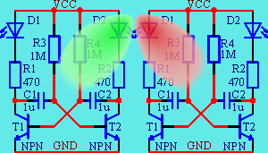
The blinky on the left is possibly the simplest and the best known electronic circuit of the world. To me it has a special meaning too, because it was the very first electronic circuit I assembled 40 years ago.
Full documentation of an open HW PCB is here, and sample PCBs can be bought in the shop.
Is it the cheapest, the smallest, the simplest or the smartest of all blinkies?
NO, NO, NO, NO. It is not even the oldest. Similar blinkies can be made using vacuum tubes, relays, pneumatic and even mechanical components, and those existed long before the first transistor.
It is the toughest challenge, because that old blinky is really a cheap one. The component cost, without LEDs and connectors, is about €0.01, and the PCB is about €0.01 too.
Back in the seventies transistors were expensive, so the measure of complexity was the number of transistors. And, because it is possible to make a blinky with only one transistor, there were ways to make it simpler.
Today, in 2020, transitors are cheap, €0.0025/pcs. Resistors have always been cheap, less than €0.0002/pcs. So it is quite possible that the most expensive components of the circuit are the capacitors. But only if the blinking frequency is less than 1Hz, because capacitors up to about 1µF cost less than €0.001/pcs.
Using complementary transistors, it is possible to get rid of one or two resistors, and use only one timing capacitor. The expected price saving is about €0.001/pcs. It may seem small, but it is about 5% of the total costs. In a real product, 5% may be the difference between success and failure. The complementary transistor design is especially good, if we do not need two alternately blinking LEDs, but only one.
Smaller also often means cheaper. By using the complementary transistor design and the smallest possible packages, the PCB can be reduced to half of its size. That means €0.005, or 25% of total costs, savings.
The size of the timing capacitor can be a limiting factor. Smaller value timing capacitors would mean higher value timing resistors, and the 1MΩ value is already uncomfortably high for a bipolar transistor design. Increasing it even further might make the circuit unstable, or, if the transistors do not have sufficiently high beta and low leakage, the circuit might not work at all.
Changing the BJTs to MOSFETs removes this limitation, but discrete FETs are still more expensive than discrete BJTs. Currently, in 2020, the cheapest N-channel MOSFET is the 2N7002, for around € 0.005, and the cheapest P-channel MOSFET is the BSS84, for around € 0.008.
If this blinky were important enough to justify the immense tooling cost of a custom IC, then the timing capacitor would be the most difficult part to integrate into the chip. Probably a high frequency oscillator, and a clock divider circuit would be a better solution.
Adding more functionality to a discrete design is only possible by changing component values and/or adding more components. This process is slow, error prone and increases price.
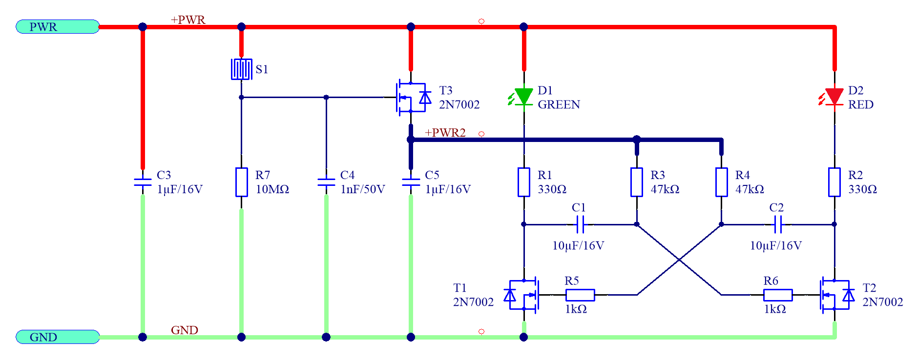
One possible addition to the blinky is a resistive touch sensor, which enables the circuit and controls the blinking frequency.

The cheapest microcontroller today, in 2020, is the Padauk PMS150C. It costs €0.021, which is ridiculously low for a microcontroller, but it is still more than our entire original circuit.
STM8S003F3P6, the cheapest reprogrammable microcontroller with a nice set of communication interfaces, costs €0.16, which is prohibitively expensive for such a simple task as a blinky, but could be used to make a bit more complicated, and less price sensitive, circuit a lot smarter.
Once the microcontroller is there, it can be used to generate complicated patterns, accurate and easily changeable frequencies, and respond to inputs in a variety of ways. Adding new functions is simple and fast, and usually can be done without any change to the hardware.
Microcontrollers often need a better regulated power supply than discrete circuits, and may not be able to drive even a high power LED, without an external transistor. This is true for all applications, where microcontrollers are used for replacing discrete circuits, and it increases the price.
Writing programs for cheap microcontrollers is more difficult than writing programs for PCs, and for mainstream 32-bit microcontrollers. Quite often the only tools we have are a basic assembler and a simple programmer. For STM8, we are lucky to have a good C compiler and a real debugger.
Once we accepted the high initial cost of the microcontroller, these come for almost free.
With discrete components it is difficult to get a better than ±50% accurate frequency, mainly because of the high tolerance of the capacitors. With a microcontroller we get ±5% accuracy out of the box, which can be increased to ±1% accuracy by calibration, and to 30ppm accuracy by using a crystal oscillator.
Microcontrollers can test themselves and get feedback from the environment, so they are well suited for applications which require high reliability. Two microcontrollers, checking each other all the time, and controlling the blinking independently, offer much higher reliability than any number of discrete components would. Suppose the blinky is used to control a lighthouse signal, and any failure would threaten the life of thousands of people. I would be happy to design such a circuit, but unfortunately, it is beyond the scope of this document.